
| Interface Module (IM2) (40) The J1 connector - connects the copper transistor driver circuits and feedback circuits from the motor control ECM. The system power and ground supply circuits from the terminal blocks and the system power and ground supply circuits to the phase modules are also connected through this connector.(41) The fiber optic circuit connections for the motor control ECM transistor driver circuits and the transistor feedback circuits. |

| Interface Module 1 and Interface Module 2 fiber optic connector assignments |
Note: The circuit connections for the interface modules 70 contact J1 connectors are illustrated in the "System Schematic" section in the back of this manual.
Each motor control ECM uses an interface module to aid in the control of the transistors in the phase modules. Motor 1 ECM uses the Interface Module 1. Motor 2 ECM uses the Interface Module 2.
The interface modules are identical. Each interface module uses the same identical version of software. Consequently, the interface modules can be switched, without flashing software, in order to determine if a suspected problem is present in a specific module.
The J1 connector grounded location code circuits indicate to the software which position and ECM that each interface module is paired with. Based on this information, the appropriate control software functions for the specific module position will be activated.
The functions of the interface modules are:
- Primary function is to isolate the low voltage ECM control circuits and the phase module power supply circuits from the high voltage circuits that are present inside of the phase modules. This isolation ensures that there is no possibility that a short circuit between a high voltage circuit and a low voltage circuit can occur. The fiber optic circuits also ensure that electrical fields cannot accidentally cause transistor activation.
- Supply system control voltage to the bulk capacitors. In the event of a system power loss, the bulk capacitors will provide approximately 3 seconds of emergency power in order to allow the interface module to activate an orderly shutdown of the power transistors. The emergency power avoids possible short circuits of the DC bus that can be caused by erratic switching of the transistors at a control voltage that is too low.
- Interface Module 1 controls the operation of the Chopper Module based on commands from either of the motor control ECMs or the Drivetrain ECM.
- Interface Module 2 controls the operation of the Crowbar based on commands from Interface Module 1, either of the motor control ECMs or the Drivetrain ECM.

| Motor control ECM and interface module enable and enable feedback circuits |
The operation of the interface modules is enabled by the motor control ECMs. When the key start switch is moved to the ON position or when the Engine is started, the ECM will determine if any drive train related diagnostic codes or level 3 Events are active. If no faults are active and the system conditions are correct, each motor control ECM will use the following logic to enable or disable the operation of the interface modules:
- Motor 1 ECM will ground the normally high enable circuit at contact J1-63 (IMEN1) in order to enable Interface Module 1 and supply one of two required enable signals for Interface Module 2.
- Motor 2 ECM will ground the normally high enable circuit at contact J1-63 (IMEN2) to supply the second enable signal in order to enable Interface Module 2
- If one or more of the ECM enable signals for either interface module is interrupted or lost, Interface Module 2 will activate the Crowbar to disable drive train operation.
- Each interface module acknowledges to each motor control ECM that the enable signals have been received by grounding two feedback circuits at contacts J1-18 and J1-43 (Interface Module 1,FB1A, FB2A - Interface Module 2, FB1B, FB2B).
- If either motor control ECM detects that one or both of the feedback circuits from the interface modules is interrupted or lost, the retarding contactors and the chopper module will be activated in order to disable drive train operation.
- Once enabled, each interface module will monitor the status of the 24 VDC system voltage input and the isolated 24 VAC power supply output that is sent to each phase module. If either of these power supplies is detected to be too high or too low, the interface module will send a diagnostic feedback voltage signal (circuits EVNT1, EVNT2) back to the controlling motor control ECM. A feedback circuit voltage of 2.0 to 4.0 VDC indicates that the power supply voltages are in tolerance (22.4 VAC to 23.2 VAC). A feedback circuit voltage of less than 2.0 VDC indicates that a low voltage has been detected (21.5 VAC or less).
- A diagnostic feedback voltage signal of less than 2.0 VDC or a loss of the diagnostic feedback signal from either interface module will result in activation of the Retarding Contactors and the Chopper Module in order to disable drive train operation.

| Interface module isolation of the phase module control circuits |
Each motor control ECM will use two separate power transistor pairs in each phase module to create one of the three phases of AC voltage for each of the traction motors.
Each transistor pair has an internal electronic transistor gate driver circuit. The gate driver requires a voltage input from the ECM in order to turn the transistors ON. Each transistor pair sends status feedback back to the ECM on a feedback circuit. Consequently, each phase module requires two driver circuits from the ECM and supplies two feedback circuits back to the ECM.
System voltage 24 VDC is supplied from the machine fuse panel. The power circuits are connected to the interface modules through the terminal blocks in the cabinet. The interface modules supply isolated 24 VAC power and ground supply circuits to the phase modules. The AC power is required to power the internal electronics for the gate driver control circuits and the feedback circuits. The power is supplied to each transistor pair in the phase module.

| Disconnected interface module fiber optic connector - each fiber optic connector on the interface module is for one circuit. |
Fiber optic gate driver circuits and feedback circuits provide isolation between the low voltage control circuits and the high voltage circuits in the phase modules.
The interface modules convert the voltage pulses of the ECM driver circuits to light pulses. The light pulses are sent to the phase module through plastic fiber optic circuits. The internal electronic gate driver for each transistor pair converts the optical pulse back to a voltage pulse in order to activate the transistors.
The status feedback signal is sent back to the interface module as light pulses through a separate fiber optic circuit. The interface module converts the light pulse back to a voltage pulse and sends the signal back to the ECM on a copper circuit.
The interface modules receive the system power supply and use internal transformers to provide isolation of the power supply circuits. One isolated 24 VAC power supply is supplied to each phase module. The AC power provides the power for the internal electronics of the transistor pairs . A transformer inside of the phase modules is also used to isolate this power supply.
At Engine start, the controlling ECM will perform an automatic test to check the status of each transistor driver and feedback circuits. If the expected result of these tests are not detected, the drivetrain system will not be enabled.
A Cat ET test is available that enables a technician to perform a key ON test for each transistor pair. The test will allow the user to turn ON single ECM transistor driver circuits. The user can check the operation of the driver circuit, the power transistor pair, and the feedback circuit. When a circuit is turned ON, the fiber optic circuits can be disconnected and the light pulses can be visually verified to be present.
Refer to the Testing and Adjusting, "Power Transistor - Test" section of this manual to learn more about this test.
Motor 1 ECM and the Interface Module 1 also control the operation of the Chopper Module. The Chopper Module is a phase module that is identical to all the other phase modules, however, only one of the transistors pairs is used. A fiber optic driver circuit and feedback circuit is used to control the Chopper Module. The Chopper Module will be discussed further in the "Phase Modules" section.
Interface Module 2 controls the activation of the Crowbar according to signals that are received from either of the motor control modules. The Crowbar is used to discharge the DC Power Bus immediately if certain severe fault conditions occur in the system. A fiber optic driver circuit is used to activate the Crowbar. When the Crowbar is activated, the DC Power Bus positive bus and the negative bus are connected together through the chopper grid 1 resistor elements. Activation of the Crowbar effectively shorts the bus and immediately discharges the bus voltage in a short time period. The operation of the Crowbar is discussed in the "Crowbar" section that follows.
Note: The fiber optic connectors on the interface modules and on the phase modules require special handling to avoid damage when connecting or disconnecting the connectors. Refer to the Testing and Adjusting, "Fiber Optic Connector Handling" section of this manual for guidelines on the handling of the fiber optic connectors.
2.- Phase Modules

| The phase modules and the chopper module that are assigned to each Motor ECM |
The phase modules and the Chopper Module in the Inverter Cabinet contain the power transistors that are used to create each individual power phase for the three phase traction motors.
In the Inverter cabinet, the phase modules are labeled "PMA1", "PMB1", "PMC2", "PMA2", and so on. The "PM " stands for phase module. The "A", "B" or "C" stands for the motor phase. The "1" or "2" stands for Traction Motor 1 or Traction Motor 2.
In order to identify the correct phase module in the cabinet, in this manual the phase modules will be referred to in the following format: "Motor 1, Phase A Phase Module (PMA1)" or "Motor 2 Phase A Phase Module (PMA2)".

| ECM control circuits for the operation of one traction motor control phase module |
The phase modules and the Chopper Module that are installed in the Inverter Cabinet are physically identical. Each of the phase modules contains two transistor pairs. Each pair consists of two power transistors that are connected in parallel between the positive DC Power Bus and the negative DC Power Bus. The parallel connected transistors are used in order to handle the high current loads that are required for traction motor operation.
An AC bus is connected between the two sets of transistors. This AC bus is connected to one of the 3 AC phase cables that will go out to the traction motor.
The set of transistors that is connected on the DC positive side of the AC connection will be used by the motor control ECM to switch the positive DC voltage in a sequence that will create the positive side of the PWM output voltage.
The set of transistors that is connected on the DC negative side of the AC connection will be used by the motor control ECM to switch the negative DC voltage in a sequence that will create the negative side of the PWM output voltage.
The ECM will activate the gate driver outputs for the three pairs of positive switching transistors and the three pairs of negative switching transistors. the ECM will use a high frequency sequence that will create the three phases of PWM output voltage. The traction motors detect an RMS voltage from the PWM pulses that resembles an AC sine wave (Refer to illustration 1).
Each transistor in the phase module has a diode connected between the emitter and the collector. The diode allows electrical current to flow in the reverse direction when the traction motors are producing a voltage output during dynamic braking.

| Phase Module (42) Cooling air heat exchanger (43) Low voltage connector for the fiber optic driver circuits, the fiber optic feedback circuits, the copper power supply circuits and the copper temperature sensor circuits. (44) Ground connection (45) Negative (N) DC Power Bus connection (46) AC output connection (AC) connection - phase A, B, or C for motor control(47) Positive (P) DC Power Bus connection |
Each phase module, including the Chopper Module, has an internal 1667 microfarad capacitor connected between the positive and the negative DC Power Bus connections. The capacitor is in place to help to absorb the voltage spikes that can be caused by the switching of the transistors. All of the phase module capacitors are connected in parallel to each other and to the system capacitance. The combined capacitance sum provides a large amount of total DC system capacitance. The system capacitance helps to stabilize the DC Power Bus voltage and provide more power during periods of heavy demand.

| Using the high voltage meter to verify that the DC capacitive voltage at the phase module is discharged to 50.0 DCV or less |
In addition to performing the "Electrical Shutdown and Voltage Discharge" after Engine shutdown, always verify that the voltage at an individual phase module is discharged. Before any contact is made with the phase module bus connections or the phase module connector, use the high voltage meter to measure for a DC voltage. Ensure that a voltage of 50.0 VDC or less is present before any work is performed.

| Phase module low voltage harness connector (53) Fiber optic driver circuits are located at contact "B" and "R" (54) Fiber optic feedback circuits are located at contacts "C" and "S" (55) Power supply circuits at contacts "L" and "M"(56) Temperature sensor circuits at contacts "F" and "G" |
The fiber optic circuits and the system voltage power supply circuits that are connected between the interface modules and the phase modules are connected at the phase module in a low voltage connector. These connectors enable connection of the two copper power supply circuits, the two sets of fiber optic driver circuits and the feedback circuits for the two transistor pairs in each phase module. In addition, two temperature sensor circuits that are connected back to the motor control ECM enter the phase modules through this connector.
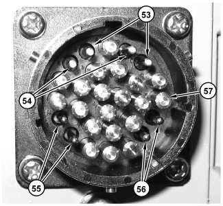
| Phase module low voltage connector (53) Fiber optic driver circuits are located at contact "B" and "R" (54) Fiber optic feedback circuits are located at contacts "C" and "S" (55) Copper temperature sensor circuits at contacts "F" and "G" (56) Copper AC power supply circuits at contacts "L" and "M"(57) Alignment posts that are used to aid in the alignment of the connectors. The posts are not used for electrical connection. |
Each transistor pair requires a transistor gate driver input from the ECM to turn the transistors ON and OFF. Each transistor pair sends status feedback back to the ECM on a feedback circuit. Consequently, each phase module requires two driver circuits from the ECM and supplies two feedback circuits back to the ECM.
The ECM driver and feedback circuits are fiber optic circuits. For more information on the fiber optic circuits, refer to the "Interface Modules" section that precedes this section.
Each transistor pair contains internal electronic gate driver control circuits that will control the operation of the transistors. The gate drivers require a 24 VAC power supply in order to operate. These isolated power circuits are supplied to each phase module from the interface module that is paired with the controlling motor control ECM.
At key ON or at Engine startup before actual transistor operation begins, the controlling motor control ECM will test the operation of each transistor pair that is under control. The ECM will send a driver circuit signal pulse to each of the power transistors pairs. If an internal problem is not detected, the electronics for each pair will answer the signal pulse with a feedback status pulse on the feedback circuit.
If this status pulse is not received by the motor control ECM in a predetermined time, the ECM will not enable drive train operation.
During machine operation when the ECM is sending driver signals to the transistor pairs, the electronics for the transistors are constantly sending a corresponding feedback signal back to the ECM. This feedback signal indicates that the operation of the transistor pair is correct.
If the ECM does not detect the feedback signal or if the signal is not what is expected by the ECM, the involved motor control ECM will immediately command the Interface Module 2 to activate the Crowbar. The DC Power Bus voltage will be immediately shorted through the Retarding Grid 1 resistor and the operation of the drive train will be disabled.
During the initial test or during machine operation, a failed feedback signal will also result in the activation of a level 3 Event by the controlling motor control ECM. For motor control transistors, E900 through E905 for "Drive Motor Phase (A, B, or C) Power Transistor (1 or 2) Signal Mismatch".
A Cat ET test is available that enables a technician to perform a key ON test that will turn ON a specific ECM transistor driver circuit in order to test the operation of the driver circuit, the power transistor pair, and the feedback circuit. When a circuit is turned ON, the fiber optic circuits can be disconnected and the light pulses can be visually verified to be present. Refer to the Testing and Adjusting, "Power Transistor - Test" section of this manual to learn more about this test.
During machine operation, the power transistors in the phase modules are cooled by air passing through the heat exchanger that is located on the top of each phase module. An antifreeze mixture is sealed in the phase module and the heat exchanger.
The heat exchanger lines up with the air intake vent on the front of each compartment. As the hydraulic cooling fan draws the air in through the intake vents, the internal liquid mixture is cooled. The liquid is naturally circulated through the phase module to cool the internal components.
A sand filter on the front of the intake air vents eliminates large particles from entering the cooling system. However, this air is largely unfiltered air. The sand filters should be checked regularly for obstructions that could cause a reduction of air flow.
Each of the six traction motor phase modules and the Chopper Module has an internal temperature sensor. Each of the temperature sensors is a 1000 ohm (at 0.0° C (32.0° F)) Resistive Temperature Device (RTD).
The temperature sensor is isolated in a section of the module where there is no possibility of short circuit to a higher voltage. The temperature sensor positive and negative circuits are connected through the phase module low voltage connector directly to the ECM. The circuits do not pass through the interface modules.
The controlling motor control ECM monitors the temperature sensor circuits for abnormal conditions. The ECM will activate a diagnostic code for a specific temperature sensor circuit if an unexpected condition is detected.
The components inside the phase modules including the temperature sensor are not serviceable. If a phase module internal component has failed, the phase module will have to be replaced.

| Phase module disconnected and ready for removal with the front connections connected with a wire (arrow) |
If a phase module or the Chopper Module is disconnected for removal, the DC Power Bus connections (P, N) and the AC output connection (AC) on the front of the phase module must be connected together with a tie wire. This tie wire connection is in place to ensure that the internal capacitor remains discharged by placing all connections at the same potential.
The phase modules weigh approximately 135 kg (298 lbs.). A removal tool is available to aid in the removal and replacement of the phase modules. Refer to Disassembly and Assembly, KENR8715 for instruction on the removal and replacement of the phase modules.
See You Soon!!!
0 comments:
Post a Comment